REVERSE ENGINEERING THE IMPOSSIBLE
Reverse engineering using 3D scan data is the most efficient way to generate a CAD model from a physical object that has any kind of complex or freeform shape. While using traditional measurement techniques such as calipers to reverse engineer these complex surfaces can be difficult or even impossible, 3D laser scanning shines – literally! Although this scan data can easily be turned into a model representing its as-built shape (a shrinkwrap model), we specialize in creating models that match original as-designed features – even parametric ones.
Take advantage of the experience of 3DScanCo’s reverse engineering team to help you:
Obtain CAD data that captures an object’s original design intent
Design a new part to fit to a legacy part
Accurately model performance surfaces
Update CAD models of your tooling to match shop-floor changes
Redesign a part without manufacturing defects
Modernize your manufacturing process
BETTER ENGINEERS= BETTER RESULTS
3D scanning is not the “easy button” that many think it is. The most critical step in the reverse engineering process is the modeling bridge performed by the applications engineers. Consequently, the reverse engineering process can be quite complex and is very dependent on the skill and expertise of both the engineers doing the work and those managing the project. The better the engineers, the better the results. At 3DScanCo, with our close ties to Georgia Tech, you know that you are working with the some of the best engineers in the world.
Our consultative, problem solving process will help you quantify performance goals and ultimately get you the deliverable you need. Whether it’s a quick surface model or a fully parametric SolidWorks file, 3DScanCo has a solution that’s right for you. Our engineers have experience working with a wide variety of CAD packages such as SolidWorks, AutoCAD, Pro/E, CATIA and Rhino, and will deliver files in any format you need.
REVERSE ENGINEERING MODEL TYPES
Our reverse engineering process outputs files in 3 major categories. However, every client’s file is further customized to meet their exact requirements, as every project is different.
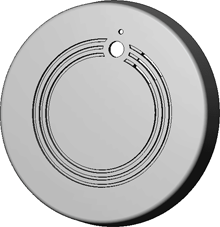
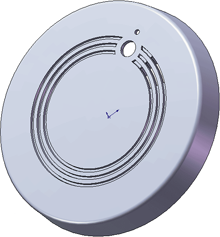
 PARAMETRIC MODEL
CHARACTERISTICS
- Ideal data converted from scan data
Can ignore or incorporate manufacturing defects
Parametric solid model
Modify model parametrically
Can be Class A surfaced
WHEN TO USE
- Modifications to the file are going to be made
2D drawings are needed
Surface finish must be smooth (for manufacturing)
Buildings parts on or around scanned part
 HYBRID SURFACE MODEL
CHARACTERISTICS
- Ideal data converted from scan data
- Can ignore or incorporate manufacturing defects
- “Dumb” IGES surfaces or solid
- Modifications require re-trimming
- Can be Class A surfaced
WHEN TO USE
- Few modifications to the file are going to be made
- 2D drawings are needed
- Surface finish must be smooth (for manufacturing)
- Buildings parts on or around scanned part
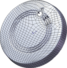
 SHRINKWRAP SURFACE MODEL
CHARACTERISTICS
- Captures as-built state
- Includes manufacturing defects
- Patch-work of small surfaces
- Non Class A surface finish
WHEN TO USE
- Need as-built state
- Designing parts to fit as-built state
- Surface finish is not critical
- Free form shapes such as teeth, bones, sculptures, and custom-fit molds
