 3D SCANNING MYTHS AND MISCONCEPTIONS
AUTOMATIC CAD MODELS
3D scanning is a fast and accurate means of capturing physical measurements from real world objects. The common misconception is that 3D scan data is a CAD model because it is captured and viewable in 3D on the computer. However, there is a distinct difference between a CAD model and 3D scan data.
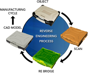
A CAD model is based on ideal mathematics i.e. a plane is infinitely planar and a cylinder is a mathematically perfect cylinder. In CAD, all of the features of the model are ideal in the true sense of the word. But once a physical object is created from this data, however it’s made, it is no longer ideal. The “non-idealness” of the object is reflected in its scan data, which is just a collection of physical data points that represent the physical real-world object. The challenge of reverse engineering is to detect the original design intent (the original ideal model) based solely on the physical measurements of the object. We call this the “Reverse Engineering Bridge” from scan data to CAD.
CMM MISCONCEPTIONS
Coordinate Measuring Machines are ubiquitous in data capture applications and thus are seen as the standard to which all other 3D scanning technologies are compared. Situational analysis can be used to determine which technology (CMM, non-contact or any combination of the two) will meet the needs of a specific application. There are situations, however, where the accuracy and repeatability of CMM technology is uncertain; here are two common sources of error.
- User Error – Improper datum schemes can lead to large inaccuracies in measurements. The datum feature is often manufactured with a lower tolerance then the check feature, resulting in a questionable measurement. Datum schemes are typically setup by a CAD designer without the necessary metrology experience. This situation is hard to avoid or eliminate, therefore it is a limitation to the accuracy of the technology. User error can also occur if the CMM is being used to manually take measurements.
- Probe Compensation – CMMs use a technique called probe compensation to predict the measurement location of the touch probe. This technique relies on an accurate approach vector to the object which is typically taken from the ideal CAD model of the part being inspected. However, the object being inspected is a physical object and therefore cannot be the ideal shape as described in the CAD model. As a result, the approach vector cannot be accurately predicted, resulting in inaccuracy that cannot be avoided.
- Other sources of inaccuracy can be temperature compensation, inaccurate or non-repeatable fixturing and/or rigidity of the table and arm.
NON-CONTACT 3D SCANNER MISCONCEPTIONS
Quoted accuracies from the manufacturer are averaged volumetric measurements under ideal measuring conditions. These tests allow for inaccuracies to be numerically eliminated. The two main causes of non-contact inaccuracy are noise from lighting conditions and changes in shape of the measuring device due to temperature variation. When the volumetric data captured is compared to the expected volumetric shape, the overall average deviation is small, but the point to point variations are typically larger than the quoted accuracy. Noise in the measurements can lead to downstream problems such as waviness in surface data or inaccurately predicting the location and orientation of CAD features.
