SITUATION

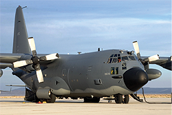
MC-130E Talon I
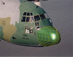
Since its introduction in the 1960s, the MC-130E Talon I has been modified on a nearly continuous basis to incorporate more and more modern technology into its legacy design. One such addition is of a state-of-the-art radar system which would be housed inside a radome that was hand-crafted from fiberglass in the 1950s.
Computer Aided Engineering (CAE) would have to be performed by the client to test a variety of functions of the radar system inside the radome. To perform CAE, they would need CAD data of the legacy part radome, which has never been modeled before for the MC-130E Talon I. The exact shape of the radome is critical for proper testing of the radar system inside, as only a couple inches separate the inside wall from the equipment.
SOLUTION

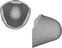
Radome Scan Data
Our team was contracted to scan a Fulton and Non-Fulton version of the radome and generate CAD data accurate to .01 inches at specific areas. Our engineers used the Konica Minolta Vivid 9i in conjunction with photogrammetry to generate scan data accurate to .002 inches. The high resolution scan data would be used to perform all the reverse engineering processes needed to generate CAD of the radome.
Using the Rapidform software suite, our team reverse engineered and modeled the radomes to within the accuracy tolerances. Rapidform allowed for the modeling of the critical surface features, such as the interior surface curvature and bolt hole locations, to be as accurate as possible while remaining curvature-continuous for aerodynamic and electromagnetic testing of the radar system.
RESULTS

MC-130E Talon I Radome Data
The resulting CAD data from our team’s reverse engineering was hugely successful for CAE performed by the client. Because CAD data did not exist for these radomes, and because our team’s CAD models performed so well during testing, the client is interested in contracting our team to scan newer and much larger radomes in the future.
“Please let your team know we appreciate the effort put forth. …We will not hesitate to utilize you in the future as opportunities arise.” – Dave
